 Tutorials
Books
Videos
Forums
Tutorials
Books
Videos
Forums


This is an archived tutorial from the kirupa.com legacy collection. It covers software that may no longer be available, but it is kept online because the ideas still hold up.
One of the major features in Flash Player 10 is the ability to have 2d elements frolic around happily in a 3d environment. Of course, no feature in a runtime is useful without the ability for someone to actually create content using that feature easily. Fortunately, Flash CS4 contains a few tricks up its sleeve that make it very easy for someone to take advantage of this 3d functionality. This article will provide an overview on how you can use the 3d tools inside Flash.
This article discusses how to use Flash CS4 to work in 3d. This means there is a lot of pointing and clicking. If you want to learn how to use 3d using nothing but ActionScript 3, click here.
Before we look at what Flash CS4 does with 3d, I think it is important to take a step back and get an introduction to 3d concepts you will see throughout this article and elsewhere.
The three common dimensions are represented by x, y, and z. You are probably most familiar with the x and y dimensions that you've had in Flash from the very beginning:

With Flash Player 10 and Flash CS4, you still have the ability to display and create two dimensional content. What you now also have is the ability to take your two dimensional content and manipulate it in a three dimensional world with the introduction of the z axis:
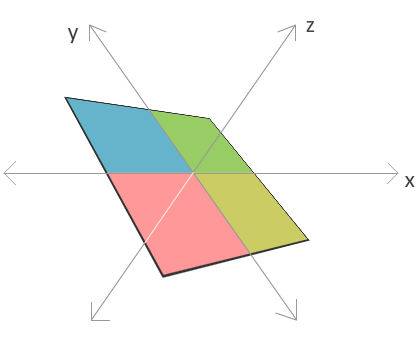
Forget for a minute everything you know or may have heard about the z axis. Think of it as just another line on which you can place your content on. You've already seen what happens when you set your x and y values. What happens when you set the z value on an element? Let's look at a few examples.
First, take a look at the following diagram for what happens when your z value is decreased:
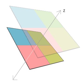
Your shape seems to get larger. When your z value increases, the exact opposite effect happens where your shape seems to get smaller:
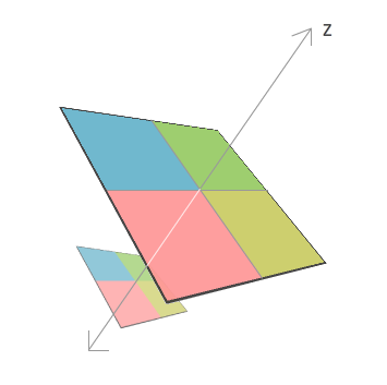
The reason is that, the z axis is often said to represent depth. Imagine you are swimming in the water, and how deep you are diving in the water is representing by your z value. If you are just floating around in the water, the equivalent of your default depth, your z value will be 0. As you start diving deeper, your z value increases. For someone looking at you from the surface, the deeper you go, the smaller you start to seem. The closer to the surface you get, the larger you seem with the z value getting smaller to represent the shallowness of your drive.
In all of these examples, I've skewed the x, y, and z axes a bit so that you can get a better feel for the relationship among the three axes. Realistically, by default, you will always see the x and y axis in their familiar north/south and east/west orientations. The z axis is perpendicular to your computer screen, so it's orientation is almost like an arrow that is shooting straight at you:

In most representations of 3d, the z axis is often designated as a hollow circle (as shown in the above image) or a circle with an x inside it. This is only important if you are designating direction. A hollow circle means the z axis is coming towards similar to an arrowhead. The hollow circle with an x means the z axis is going away from you - kind of the like the four feathers that make up the tail of an arrow that is moving away from you. Aren't you glad you know that?
In the next section, we'll go beyond the concepts and look at the code that will allow you to manipulate your content in 3d space.
In the previous section, you received an overview of how to think about perspective transforms in Flash. In this page, let's start to use Flash CS4's 3d tools.
First, create a new Flash CS4 document. Once you have created your document, draw a shape on your stage that you can manipulate. I am going to keep the four-colored square I have shown you all this time as my example:
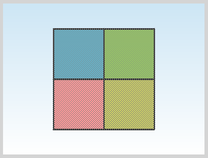
[ I drew a simple shape made up four squares ]
Once you have your shape, you need to convert it into a Movie Clip. To convert a selected object into a movie clip, select it and press F8 (Modify | Convert to Symbol) to bring up the Convert to Symbol dialog:
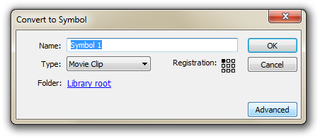
[ the Convert to Symbol dialog will allow you to create a movie clip ]
From the Convert to Symbol dialog, make sure Movie Clip is selected in the Type combo box, and hit OK. This will have converted whatever you had into a symbol - a movie clip symbol to be precise.
To quickly take something and rotate it in a three-dimensional plane, you will use the 3D Rotation Tool. To use the tool, make sure your movie clip is selected and look over in your Tools panel. Find the icon for the tool that looks like a sphere with lines going around it:
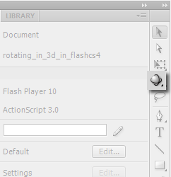
[ click on the 3D Rotation Tool to get into 3d rotation mode ]
This icon represents the 3D Rotation Tool, so once you have found it, go ahead and click on it. Once you have clicked on it, look at the movie clip that you originally had selected. Notice that its center point now has a different adorner on it:
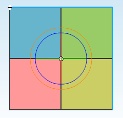
[ this crosshair-like adorner allows you to rotate in three axes ]
To make this a bit clear, let me decrease the opacity of my movie clip:
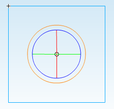
[ here is a more detailed look at the adorner ]
The crosshair that you see is what you will use for manipulating your movie clip in 3d space. While it may not look like much, this clever design allows you to rotate in the x, y, and z dimensions using only your mouse.
Each line in the cross hair represents an axis you can manipulate. The red line represents the x axis, the green line represents the y axis, the blue line represents the z axis, and the orange line is a free-for-all all axis manipulator.
For example, to rotate your movie clip horizontally via the x axis, hover your mouse over the red line. The mouse cursor will change to display a small x:
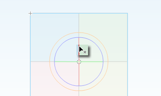
[ the cursor indicates that I am over the x axis line ]
When your cursor changes to display the letter of the axis you are manipulating, simply click and drag:
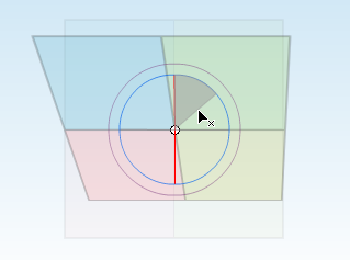
[ as I a drag on the x axis line, the circle fills in with the angle of rotation ]
As you are rotating, the cross hair doubles up as an angle indicator giving you an approximate quantity of how much you have changed the orientation of your movie clip on the x axis. Manipulating the y and z axes follow pretty much the same steps - hover over the axis line, click, and drag:
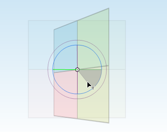
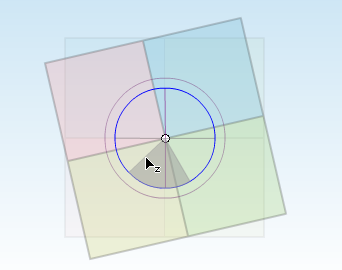
The only slight exception to this consistency is dragging the circular orange line that encloses the crosshair. Like I mentioned before, clicking and dragging on this line allows you to manipulate all three axes at the same time, but you will not see your cursor change, nor will you see the crosshair filling in to give you an indication of how much has actually changed:
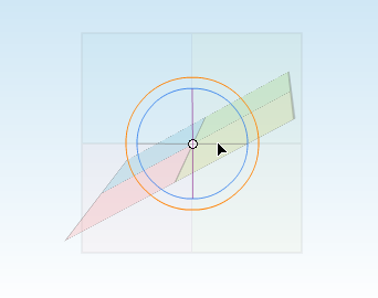
The 3D Rotation Tool allows you to only rotate your shape in the three axes. In the next section, let's look at the 3D Translation Tool that allows you to move your 3D content in a whole new way.
In the previous section, you learned how to use the 3D Rotation Tool to rotate your movie clips in the x, y, and z axes. In this page, let's look at how a few more tricks.
You have another tool in your arsenal that you can use for modifying the 3d properties of an element, and this is your 3D Translation Tool. This tool allows you to actually move your object in the x, y, or z axes. You can access the 3D Rotation Tool by clicking on the same icon for the 3D Rotation Tool that you clicked on earlier:
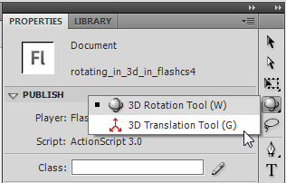
[ the 3D Translation Tool is the second item in the 3d tools menu ]
Once you have clicked on your 3D Translation Tool, make sure to click on your movie clip if it didn't have selection already. You will see overlayed on top of your movie clip two arrows and a black dot:
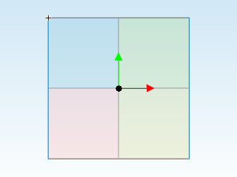
[ your 3d translate adorners should appear over your movie clip ]
The green and red arrows allow you to translate your movie clip in the y and x axes respectively. The black dot, which is actually an arrow coming out towards you, allows you to translate the movie clip in the z axes.
Before translating, make sure your movie clip does have some 3d rotation applied to it. Translating something that doesn't have any 3d effect applied to it is not very useful, so my movie clip looks like the following image:
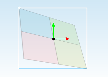
Just like you did for 3D rotation, hover your mouse over any axis, click on the arrow head or black dot, and drag in the direction the arrow is pointing. For the dot, you will have to drag up. Notice that as you are dragging, the 3d rotation you applied begins to look a bit different:
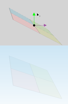
[ an example of how the movie clip is skewed as I move it up ]
From the above image, notice that your movie clip was less flat originally. Translating the y axis upwards caused it to become more flat. Adjusting the x and z translation values will produce similar results where your object will be skewed a bit more than what it was originally.
The final thing related to 3d in Flash CS4 I am going to be talking about is the vanishing point. For 3d elements, how they appear to you depends on a frame of reference known as the vanishing point. To help explain this, let me show you a picture first:
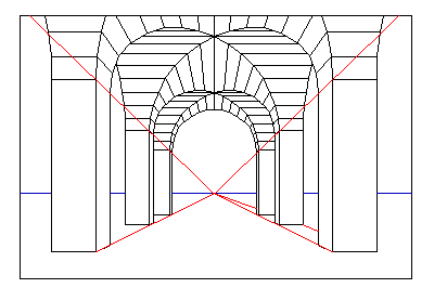
( example of the vanishing point for an arch, click for source )
The above image is a perspective diagram representing a series of arches that converge on a horizon line. The position of the point where the red and blue lines converge define how your eyes perceive what the arches look like. This point where the parallel blue and red lines converge is what is known as the vanishing point. While it makes more sense in the real world, even in Flash CS4, a vanishing point exists as well, so let's look at how to modify it.
To adjust the vanishing point, select any movie clip with your cursor. You do not have to be in 3D Rotation or Translate mode. With a movie clip selected, look in your properties panel at the category labeled 3D Position and View. Within this category, look in the area represented by the icon of a trapezoid being skewed:
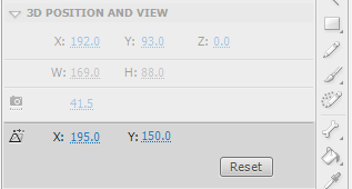
That area contains the properties that allow you to alter or reset the vanishing point. The X and Y properties displayed represent the X and Y position of your vanishing point, and by default, this point is at the center of your stage:
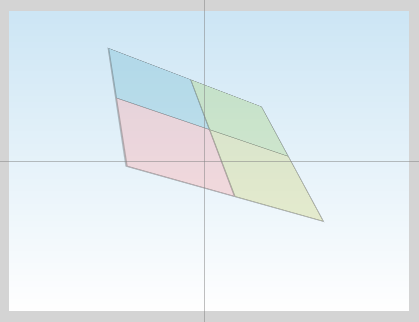
If you were to adjust your vanishing point, the intersecting lines will reposition themselves accordingly. What is more cool, though, is seeing how your movie clip looks after having the vanishing point altered:
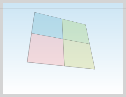
Your movie clip looks different not because you physically adjusted your shape's 3d rotation or translation properties. Because your 3d rotation and translation depend on the vanishing point's position, adjusting the vanishing point automatically corrects any 3d rotation and translation properties as well.
Alright, we are almost done with this tutorial. In the next section, I will tie up some loose ends and wrap things up.
In the previous section, you learned about fun things like the 3D Translation Tool and the Vanishing Point. That largely sums up the features inside the Flash CS4 UI relating to 3d this article will discuss. In this page, I am going to just discuss some issues that you may run into when using the 3D functionality.
Despite the coolness of all this, there are some limitations to how much you can do in Flash without resorting to writing a lot of extra code or looking at using 3rd-party 3d libraries.
When publishing your movie that has 3d applied to it, you may find that the file size of your overall project increases. The reason for this increase is that the 3d effects you see require ActionScript code that is generated for you behind the scenes. The addition of this AS3 library that contains the 3d functionality accounts for the additional file size increase. All around genius, Trevor McCauley (aka senocular) wrote about this earlier, and you can learn more about that in his post: Flash CS4- The Overhead of 3
One of the drawbacks of the 3d functionality in Flash is that whatever element you are attempting to manipulate in 3d space is automatically converted from a vector into a bitmap. Using the 3D Translation or Rotation Tools with even a minor nudge in a specific direction is enough to rasterize your vector into a bitmap.
A perfect vector shape such as the four squares that I've been using throughout this tutorial looks pretty good when viewed at its default size. Once you start zooming in, notice that the classic banding/blurring associated with bitmaps are visible:

[ oh the blurriness! ]
Besides the visual artifacts, as you can imagine from manipulating actual images instead of vectors, performance suffers a bit as well.
When shapes move in three dimensions, interesting collisions and intersections are possible. Unfortunately, this is something that isn't possible with the functionality available today. For example, imagine you have two parallel rectangles placed near other as shown below:
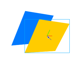
If I were to rotate the blue rectangle, in the real world, it would seem like a portion of the blue rectangle's edge will go through the yellow rectangle that is directly adjacent to it. Instead, what happens is that the blue rectangle rotates without taking the yellow rectangle into account:

This looks a little weird. It is almost as if each element has its own 3d universe based on its z-order instead of coexisting in one large universe where interactions and collisions are possible.
Just a final word before we wrap up. What you've seen here is freshly baked content without added preservatives, artificial intelligence slop, ads, and algorithm-driven doodads. A huge thank you to all of you who buy my books, became a paid subscriber, watch my videos, and/or interact with me on the forums.
Your support keeps this site going! 😇


:: Copyright KIRUPA 2026 //--